Page 1 of 2
Wiring Upgrade Schematic in Color!!!
Posted: Tue Nov 07, 2006 9:12 pm
by Desmo_Demon
I thought that before I modified the wiring on my Paso, I'd modify the wiring schematic in hopes that I'll have a better understanding of what I'll need to do, so....
Here's the wiring upgrade schematic. If any thing needs to be changed, please let me know, and I'll make the changes. Thanks.
Posted: Thu Nov 09, 2006 2:31 pm
by Desmo_Demon
Two days, over 30 views, and no one will confirm that this looks correct? :umm:

Posted: Thu Nov 09, 2006 7:52 pm
by Finnpaso
Surely it looks great, but sorry, that no time to look every wire... :laugh: btw, if nowbody is interested, You can sell that in some art shop for very high price...
U did very good job!!!!

Posted: Thu Nov 09, 2006 9:52 pm
by Desmo_Demon
Finnpaso wrote:Surely it looks great, but sorry, that no time to look every wire... :laugh:
Sorry, I actually didn't think about someone not having any idea where to look for the additional relays. I've spent so much time with the factory schematic and this one, I feel like I have them memorized.
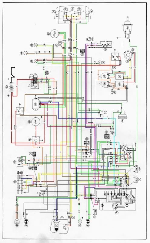
The schematic is the factory one, except for a couple of small changes to add the two relays. The only wires to check for accuracy with the wiring upgrade would be those attached to the two relays.
The first relay is just left of the voltage regulator (#21) and the starter (#19). This one shows:
1) The added red wire from the starter relay (#18) going to the added relay
2) The added ground
3) The two sections of spliced brown wire from the fuse block (#17) to the ignition switch (#10).
The second relay is drawn just above the two ignition modules and coils (#24, 25, 28, and 27). This shows:
1) The red wire ran from the starter relay (#18) to the new relay
2) The added ground
3) The spliced orange wire that went to the coils (#25 and #28) from the kill switch (#16).
For anyone not familiar with this upgrade, go to either of these two links to find out more about it....
Wiring Upgrade - http://www.frontiernet.net/~jcslocum/75 ... 20rev1.pdf
Discussion of the Upgrade - http://forums.ducatipaso.org/viewtopic. ... opic&t=173
I think this should assist anyone who stumbles across this thread in a future search.
Posted: Fri Nov 10, 2006 6:48 am
by Skins

I'm completely stupid when it comes to electrics, although I did manage to install the relay upgrade designed by Paso750 and Jon Slocum, which made a real difference to my starting, so I don't feel qualified to approve the altered schematic. But I can see where the additions have been made, although it's been done so professionally it's not easy to see without your directions.
However I am an artist, and I can assure you it's a very pretty work indeed.
Posted: Fri Nov 10, 2006 7:36 pm
by motiztab
Sure looks good to me.
Printed both off and yes it looks right to me.
Well done saves me printing something up for my file on the bike!!
Cheers
Posted: Fri Nov 10, 2006 8:34 pm
by Desmo_Demon
motiztab wrote:yes it looks right to me.
Excellent!
I will soon offer a HUGE version of this that is downloadable from my website (like the large factory wiring schematic I have). I'll post a link after I upload it to my server.
If anyone needs a copy emailed to them, just PM me with a request.
Posted: Mon Nov 13, 2006 10:12 pm
by jcslocum
I'll print it and look at it tonight.
Posted: Wed Nov 15, 2006 12:01 pm
by jcslocum
Terry,
It looks correct. I had a hard time telling the old from the new! You should add a few notes regarding the relay and fuses with call out boxes. A dotted line box around each relay would also help illuminate the difference.
Excellent work.
Thanks!
Posted: Tue Nov 21, 2006 9:34 pm
by Desmo_Demon
jcslocum wrote:You should add a few notes regarding the relay and fuses with call out boxes. A dotted line box around each relay would also help illuminate the difference.
I've played around with this a couple of times and it never looks correct to me. I'm having a difficult time throwing in a dotted-line box or circle with the freebie software I'm using. I do agree that, unless you are specifically looking for the mods, you will have a difficult time distinguishing them.
I thought about doing another one with all untouched wires in black and only the mods in color. Maybe that would be an idea for a third diagram. We'd have the original one in color, one showing just the wiring mods in color, and the last one to show an existing bike with the wiring mods with everything color. I did this one, as it is now, for a bike with existing mods, not as a visual aid to doing the wiring mod.
Posted: Tue Nov 21, 2006 11:51 pm
by jcslocum
The third option would be great. The ability to just see what's going to change would be very helpful.
Posted: Wed Nov 22, 2006 4:19 pm
by Desmo_Demon
jcslocum wrote:The third option would be great. The ability to just see what's going to change would be very helpful.
Here you go, Jon......
Posted: Wed Nov 22, 2006 4:42 pm
by jcslocum
I will add this to the upgrade instructions.
Nice work!
Posted: Wed Nov 22, 2006 4:55 pm
by Finnpaso
Posted: Wed Nov 22, 2006 5:43 pm
by Skins
Here! Here! Excellent!