Page 1 of 3
Another question about clocks!
Posted: Mon Nov 26, 2007 4:39 pm
by kirk332
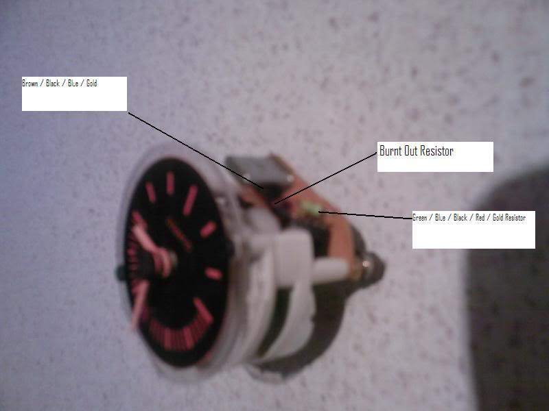
As you can see not a very good picture, I need a new camera Santa!! My clock is not working and for a very good reason, I have a resistor that has burnt out and I can't tell what resistance value it is because it is completely black. Has any one managed to find a circuit diagram for these clocks as yet? I have done lots of surfing but to no avail. Some of the previous posts, on this subject, suggest these clocks are rubbish however I would like to try and get it working again if possible. I need help in trying to identify the colour coding on the resistor so if any one has a spare clock lying around could you please have a look and try to identify these colours for me please. I think you should be able to identify the one in question however if you need a better photo I will disassemble it further and get a better quality photo taken for you.
Cheers
Re: Another question about clocks!
Posted: Tue Nov 27, 2007 6:02 am
by redpaso
Clocks have no place in motorcycling, Riding is all about freedom & that means not watching the clock. put it back in place & forget about it. Enjoy riding & forget the rest of the world while you are doing it. We don't get enough time on the bikes as it is so we don't need to look at the clock while we do it.
")
Re: Another question about clocks!
Posted: Tue Nov 27, 2007 6:15 am
by persempre907
redpaso wrote:Clocks have no place in motorcycling, Riding is all about freedom & that means not watching the clock. put it back in place & forget about it. Enjoy riding & forget the rest of the world while you are doing it. We don't get enough time on the bikes as it is so we don't need to look at the clock while we do it.
You're right, but I understand him: I also would like my clock is working, even if I willn't see it...
I can tell, and it has been already told, the clock is the same of many FIAT cars (Panda etc.).
Has nobody a dash or a clock in the garage to see at it?
Ciao
Re: Another question about clocks!
Posted: Tue Nov 27, 2007 9:29 am
by kirk332
Yes your right about the time thing, not enough of it, but it's not about that though, it's about the challenge of fixing something that is broken and having everything working as it should. But after saying all that, sometimes I actually really do need to know what the time is and if you don't wear a watch like me, it's a pretty handy thing to have.
Re: Another question about clocks!
Posted: Wed Nov 28, 2007 12:41 am
by redpaso
Aahh the challenge of "The Fix", now that is something that I can relate to.
Maybe once you master the clock you can make up a cover so you only look at it when you really need to

Re: Another question about clocks!
Posted: Wed Nov 28, 2007 12:57 am
by kirk332
Maybe once you master the clock you can make up a cover so you only look at it when you really need to
I'll be too busy looking at the next corner!

Re: Another question about clocks!
Posted: Thu Nov 29, 2007 6:04 am
by kirk332
There must be someone out there with an old clock/instrument cluster that can have a look for me please.
Cheers
Re: Another question about clocks!
Posted: Thu Nov 29, 2007 12:17 pm
by dave906
Hi Kirk
My clock is on the bench but I have the same burned out resistor as you. Don't know what the original value is. Looking at the circuit board layout it appears to be a current limiting resistor from the 12V feed after a polarity protection diode.
Should have been no more than 100-200 ohms given the approx current draw of the clock motor is about 20mA and the motor coil impendance measures about 370 ohms (on mine anyway).
Inspired by your query I dug out the old clock and had a play. I bypassed the blown resistor with a variety of resistor values but could not get the clock motor spinning. There was no activity from the chip or the crystal oscillator so I suspect my chip is dead and whatever upset that caused an excessive current to flow through the current limit resistor which eventually 'let out the smoke'. It ran for years before dying, so I don't think it likely that it was a resistor with too low a power rating or it would have died early on.
As an alternate test I gave the motor a direct feed of a 60Hz square wave from a signal generator with a peak-peak amplitude of around 12 volts (AC around 0 volts rather than offset to oscillate between 0 and 12V). The motor ran fine and kept time.
So, I haven't fixed it yet, but it will go on the end of a long list of jobs.
For those with more time on their hands, and the urge to tinker with electronics to make up an alternative 60Hz driver circuit, the clock setup seems to be like this:
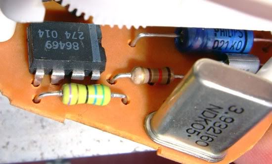
The chip is an oscillator and divider combination which divides the crystal frequency down from 3.932160 MHz to 60 Hz. It divides internally by 65536 which is 2^16 (ie a 16 bit counter/divider). I haven't been able to identify the part number or find something similar but thats what I deduce is happening.
The 60Hz output of the chip drives one side of the motor, while the other side goes to earth via a capacitor. The capacitor decouples the motor from direct ground so that when the chip switches back to 0V, the collapsing voltage in the inductive motor windings can 'float' or even drop below 0V (negative) without causing problems to the chip.
The motor is a synchronous AC motor as used in mains powered clocks in the USA and other 60Hz mains countries. It is not a stepper motor or regular DC motor. A synchronous motor keeps time through the accuracy of the frequency of the drive current. In the US mains, the 60Hz is very accurately controlled by the power companies on average over minutes and hours, not necessarily instantaneously. In the Paso clock the quartz crystal in the circuit provides an accurate timebase for the motor to lock to, using a similar principle to a quartz watch.
I haven't confirmed the above as I don't have a working unit but thats the way it looks to me from tracing out the circuit and looking at the component values and testing the motor direct with 60Hz.
I was considering using a small PIC microcontroller with the original crystal and just using the PIC to internally divide by 2^16 and drive the motor direct. Many of the PICs have a max pin source current spec of 25mA which may be just enough. If not, then a transistor driver between the PIC and motor would do it. The PIC and most other mircocontrollers run on 5VDC, so would need a regulator arrangement to protect the PIC from the bike's 12-15V main rail and spikes/noise etc.
There are other options with separate oscillator and divider components. Unless you can find a like for like chip most options will not just be a drop in part replacement, and will be more than a 5 minute job. They will need a new pcb or a Heath Robinson rig of bits on the back of the existing pcb.
cheers
Dave
Re: Another question about clocks!
Posted: Thu Nov 29, 2007 1:03 pm
by kirk332
Holy crap!

I haven't the time ATM to digest that but there sounds like some good info there mate. I am in email contact with Techtronic’s in Melbourne, I think, so will pass on this info; that’s if it's not subject to "Copy write", is it

Cheers
Kirk
Re: Another question about clocks!
Posted: Fri Nov 30, 2007 10:22 am
by dave906
no worries, go for your life.
Re: Another question about clocks!
Posted: Fri Dec 07, 2007 1:39 pm
by paso750
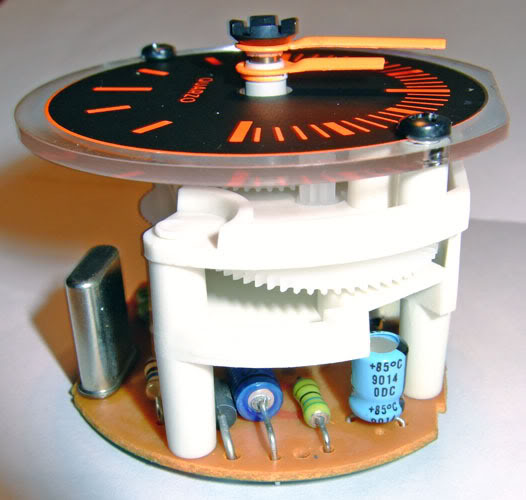
Hi there. I opened a brandnew instrument cluster to make these pics:
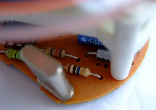
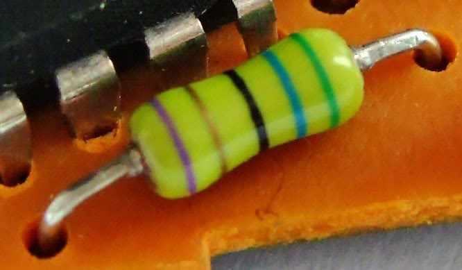
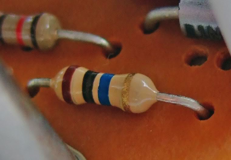
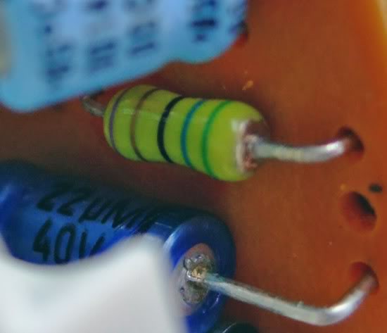
The yellow resistor appears to be a different type as the one mentioned in the very first post.
Good luck !
G.
Re: Another question about clocks!
Posted: Fri Dec 07, 2007 2:10 pm
by paso750
Re: Another question about clocks!
Posted: Fri Dec 07, 2007 2:28 pm
by paso750
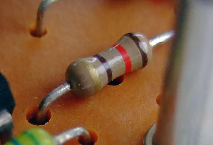
what are the values of the 4 resistors shown ? I don`t know the colour codes.
G:
Re: Another question about clocks!
Posted: Fri Dec 07, 2007 5:01 pm
by mike
Re: Another question about clocks!
Posted: Fri Dec 07, 2007 5:08 pm
by mike
let's see if I can do this:

start at the opposite end of the gold band
brown = 1
red = 2
brown = 1
120 ohms?